Wind shield, collector ring, air checker valve, upper guide bearing pads, pedestal ring, oil cooler, thrust collar, upper bracket, lower guide bearing pads, sensors, oil and cooling water pipelines, turbine guide bearing, rotating oil sump, turn buckle, self-lubricating guide vane bush, water baffle and pressure balance pipes, shaft seal housing, coupling between rotor and runner shaft were dismantled. Likewise upper bracket was overhauled followed by decoupling of main shaft and rotor shaft. Lastly rotor was overhauled. Clearance between thrust collar & upper guide bearing, upper guide bearing support & thrust collar and lower guide bearing pad was measured.
Day 2:
Lower bracket, turbine guide bearing housing, head cover, guide vanes, runner with runner shaft, bottom ring and lower labyrinth ring were dismantled and overhauled. Pressure and elongation of coupling bolts of runner shaft and rotor were measured using pressure gauge of hydraulic bolt tensioner and dial gauge during decoupling process. Dismantling was completed by the end of day 2. During night shift, eroded section of draft tube and spiral casing were welded.
Day 3:
Old Runner and runner shaft was dismantled by loosening the bolts using hydraulic bolt tensioner and was assembled with the workshop repaired runner. Pressure and elongation data during dismantling and reassembly was taken. Nuts, bolts and flanges were cleaned, remaining eroded draft tube parts were repaired by welding. Pressure balance pipe was grinded for surface smoothing and welded the corroded sections.
Day 3 was mostly cleaning and repairing the dismantled parts before preparing for assembly. Lastly lower labyrinth ring, bottom ring and guide vanes were overhauled back to turbine pit.
Day 4:
Lower labyrinth ring and bottom ring was assembled along with guide vanes. New guide vane bush was assembled with guide vane and guide vane arms was attached and marked for drilling. Most of the time were spent on drilling.
Day5:
Magnetic drilling of the guide vane arms was continued for remaining arms. Shaft sleeve was assembled with the runner shaft and finally runner along with runner shaft was overhauled and placed in turbine pit. Assembled the headcover along with guide vane bush. Turbine guide bearing housing was assembled to head cover followed by lowering of dismantled bearing top cover, oil tank and shaft seal cover in turbine pit. Guide vane arms and guide vanes were attached. Lower bracket assembly was started with assembly of lower bracket base platform followed by assembly of lower bracket base plate.
Day 6:
Lower bracket assembly was completed after the assembly of oil cooler. Stator windings were cleaned and rotor was overhauled and placed on lower bracket. Stator-rotor protective cover was assembled followed by overhauling and assembly of upper bracket. Thrust collar was heated and assembled with the rotor shaft. Pedestal ring and upper guide bearing pads were assembled on the upper bracket. Floor assembly was reassembled on top of the upper bracket. RTD sensors were tested before final connection. Runner shaft was jacket and coupled with the rotor. Respective pressure and elongation data was noted during coupling.
Day 7 & 8:
In turbine section, shaft seal housing was assembled and clearance was maintained using feeler gauge. Water baffle and rotating oil sump was assembled. Guide vanes were assembled as per the clearance mentioned in design. Servomotor was attached to the guide vane assembly followed by assembly of turn buckle and shear pin. Guide vane shutter gap was mostly maintained to zero. Pressure balance pipe was assembled followed by assembly of turbine guide bearing, RTD sensors, heat exchanger, oil pipelines, magneto strictive position sensor and air/water measuring pipelines. Clearance between turbine guide bearing pad and shaft was taken. Assembly of turbine section, lower bracket section and upper bracket section was completed. Runout test was carried out by rotating the shaft manually. Finally upper bracket housing cover and collector ring was assembled on rotor shaft.
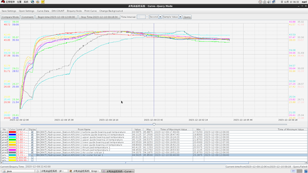
Sensor connections were finalized, air checker valve, carbon brushes were assembled and wind shield were assembled. Shutter gaps and top and bottom clearance of guide vanes were measured from the draft tube manhole. After final inspection of the assembled parts testing was started. Tail race gate, MIV and Servo lock was opened and guide vane opening was kept at 0 %. Now guide vane opening was gradually increased and shaft started to rotate at 251 rpm. Shaft vibration, bearing pad, bearing oil and air cooler temperature were noted. The guide vane opening was increased to attain 320 rpm and finally 504 rpm speed. Data were noted in every 15minutes intervals and temperature graph was monitored in control room SCADA. Temperature data followed the standard temperature saturation curve. Other parameters during no-load and load testing were satisfactory.
Installation Records:
Measurement of the Upper Bearing Pad Clearance
S.N.
Location
Pad Serial No.
Adjust Plate No.
Bearing Support No.
Clearance value (mm)
Remarks
1
(+Y)
1-81
8
8
0.05
Technical Requirement from installation record is 0.1-0.15 mm (mono-clearance)
2
2
1
1
0.15
3
(+X)
3
2
2
0.20
4
4
3
3
0.20
5
(-Y)
8-26
4
4
0.20
6
6-47
5
5
0.06
7
(-X)
7
6
6
0.06
8
44
7
7
0.06
Measurement of the Lower Bearing Pad Clearance
S.N.
Location
Pad Serial No.
Adjust Plate No.
Bearing Support No.
Clearance value (mm)
Remarks
1
(+Y)
37
1
1
0.05
Technical Requirement from installation record is 0.1-0.15mm (mono-clearance)
2
36
2
2
0.15
3
(+X)
23
3
3
0.25
4
48
4
4
0.20
5
(-Y)
41
5
5
0.1
6
30
6
6
0.1
7
(-X)
31
7
7
0.05
8
34
8
8
0.06
Measurement of the Turbine Bearing Pad Clearance
S.N.
Location
Pad serial No.
Clearance value (mm)
Remarks
1
(+Y)
2
0.20
Technical Requirement from installation record is 0.125-0.175mm (mono-clearance)
2
(+X)
3
0.05
3
(-Y)
4
0.05
4
(-X)
1
0.15
Clearance Between Shaft Seal to Housing
S.N.
Location
Clearance value (mm)
Remarks
1
(+Y)
0.95
Technical Requirement from installation record is 0.9-1.1 mm (mono-clearance)
2
(+X)
0.75
3
(-Y)
1.20
4
(-X)
1.10
Clearance Between Sealing Ring to Coupling Cover
S.N.
Location
Clearance value (mm)
Remarks
1
(+Y)
1.7
2
(+X)
1.6
3
(-Y)
2.2
4
(-X)
1.7
Measurement of the Guide Vane Shutter Gap
S.N.
Location
Guide Vanes
Clearances (mm)
Remarks
1
(+X)
16 to 1
0.00
2
1 to 2
0.00
3
2 to 3
0.00
4
(-Y)
3 to 4
0.00
5
4 to 5
0.00
6
5 to 6
0.15
7
6 to 7
0.00
8
(-X)
7 to 8
0.00
9
8 to 9
0.00
10
9 to 10
0.00
11
10 to 11
0.00
12
(+Y)
11 to 12
0.00
13
12 to 13
0.00
14
13 to 14
0.00
15
14 to 15
0.00
16
15 to 16
0.00
Measurements of the Guide Vanes Top and Bottom Clearances
S.N.
Location
Guide Vane No.
Top
Bottom
Remarks
Side A (mm)
Side B (mm)
Side A (mm)
Side B (mm)
1
(+X)
1
0.15
0.20
0.08
0.08
2
2
0.15
0.20
0.06
0.06
3
3
0.15
0.15
0.09
0.08
4
(-Y)
4
0.2
0.15
0.09
0.10
5
5
0.15
0.15
0.06
0.09
6
6
0.15
0.20
0.08
0.09
7
7
0.15
0.15
0.09
0.09
8
(-X)
8
0.2
0.15
0.09
0.09
9
9
0.15
0.15
0.10
0.08
10
10
0.15
0.2
0.09
0.06
11
11
0.15
0.15
0.08
0.06
12
(+Y)
12
0.15
0.20
0.06
0.08
13
13
015
0.15
0.10
0.08
14
14
0.15
0.20
0.10
0.10
15
15
0.15
0.20
0.10
0.06
16
16
0.15
0.20
0.08
0.06
Shaft Runout Record
S.N.
Location
Upper Guide Bearing (mm)
Lower Guide Bearing (mm)
Turbine Guide Bearing (m
1
(+Y)
0.01
0
-0.03
2
(+X)
0.05
0.03
-0.02
3
(-Y)
0.02
0.10
-0.02
4
(-X)
0.01
0.03
0
Total Shaft Runout Record
Upper Guide Bearing- 0.06 mm
Lower Guide Bearing- 0.08 mm
Turbine Guide Bearing- 0.03 mm
Record for the Tightness of the Main Shaft to Runner Coupling Bolts
S.N.
Location
Bolt number
Elongation (mm)
Pressure (MPa)
Remarks
1
(+Y)
1
0.12
60
Designed elongation 0.10 mm
2
2
0.12
65
3
3
0.12
60
4
(+X)
4
0.12
60
5
5
0.12
65
6
6
0.14
50
7
(-X)
7
0.14
45
8
8
0.12
50
9
9
0.12
50
10
(-Y)
10
0.12
50
11
11
0.12
65
12
12
0.13
60
Record for the Tightness of Rotor Shaft to Main Shaft Coupling Bolts
S.N.
Location
Bolt number
Elongation (mm)
Pressure (MPa)
Remarks
1
(+Y)
1
0.14
40
Designed elongation 0.10 mm
2
2
0.14
35
3
3
0.14
40
4
(+X)
4
0.14
40
5
5
0.12
40
6
6
0.13
40
7
(-X)
7
0.12
40
8
8
0.14
40
9
9
0.14
35
10
(-Y)
10
0.12
40
11
11
0.12
50
12
12
0.13
40
Clearance Between Runner and Upper Labyrinth Ring **