RECORD FOR GENERATOR GUIDE BEARING PAD CLEARANCE BEFORE OVERHAULING
Upper Guide Bearing Assembly
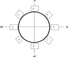
Fig: As-built position drawing for the upper guide bearing pad
Gap Measurement Between Thrust Collar to Upper Guide Bearing
S.N.
Location
Pad Serial No.
Adjust Plate No.
Bearing Support No.
Clearance value (mm)
Remarks
1
(+Y)
1-81
1
1
0.15
Technical Requirement from installation record is 0.1-0.15mm (mono-clearance)
2
7
2
2
0.05
3
(+X)
3
3
3
0.05
4
4
4
4
0.09
5
(-Y)
8-26
5
5
0.15
6
6-47
6
6
0.35
7
(-X)
7
7
7
0.35
8
44
8
8
0.35
Note: The upper guide bearing pad in the +Y direction is marked 1 and others are numbered clockwise, viewing from the top.
Clearance between Thrust Collar and Upper Guide Bearing Support
Measurement between Upper Guide Bearing Support to thrust Collar
S.N.
Location
Clearance Value (mm)
Remarks
1
(+Y)
143.13
2
(+X)
143.35
3
(-Y)
143.70
4
(-X)
142.82
Lower Guide Bearing Assembly
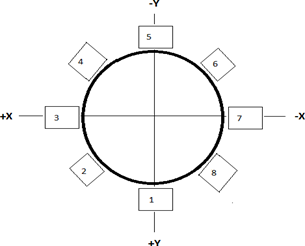
Fig: As-built position drawing for the lower guide bearing pad
Gap Between Lower Guide Bearing Pad to Generator Shaft
S.N.
Location
PadSerial No.
Adjust Plate No.
Bearing Support No.
Clearance value (mm)
Remarks
1
(+Y)
37
1
1
0.20
Technical Requirement from installation record is 0.12-0.17mm (mono-clearance)
2
36
2
2
0.40
3
(+X)
23
3
3
0.25
4
41-0
4
4
0.10
5
(-Y)
48
5
5
0.15
6
30
6
6
0.05
7
(-X)
31
7
7
0.05
8
34
8
8
0.10
Note: The lower guide bearing pad in the +Y direction is marked 1 and others are numbered clockwise, viewing from the top.
OVERHAULING WORK DISMANTLING ACTIVITIES
Activities:
a. PLANT SHUTDOWN
The MIV and Tail Race gates were closed following the shutdown of Unit-II.
Opened the spiral casing and draft tube manhole after performing the draft tube dewatering procedure.
Put Lockout/Tagout in the MIV panel, Governor Panel, LCU Panel, and Draft tube gate Panel.
Oil drained from upper, lower and turbine guide bearing oil sump.
b. OVERHAULING OF TURBINE BEARING COMPONENTS, INSIDE THE TURBINE PIT
Removed the bearing top cover’s terminal housing assembly.
Remove the oil level sensor and the oil-water mixture transmitter from the circuit.
Removed the Oil Tank Cover, oil inlet-outlet pipe, and pitot tube from the oil tank.
Disconnected the RTD and labeled the termination wires.
Remove the heat exchanger’s water input and outflow flanges, as well as the assembly base.
Remove the guiding vane’s servomotor, oil pipeline, and governor position sensor.
Using a feeler gauge, measured the clearance between the turbine guide bearing pad and the main shaft.
Removed the bearing bush assembly and jacked it up.
Removed the below-the-bearing guide ring/flange.
Removed the shear pin, split pin, and guide vane arms from the shear pin.
Removed the oil sump, support ring, press ring, and rubber strip from the rotating oil sump.
Used a pre-installed jacking machine and dial gauge to maintain shaft center alignment.
Used an impact cannon to remove bolts that have been tightened on various components.
WD-40 was used to loosen the rusty sections of the turbine pit.
Pipelines for pressure gauges and pressure control were decommissioned.
Dismantled the shaft seal housing.
c. OVERHAULING OF LOWER BEARING COMPONENTS
Removed the lower bearing assembly’s oil and cooling water inlet/outlet piping.
Removed the lower guide bearing seal cover and dismantled it.
Disconnect the RTD sensor and label the wire network that it belongs to.
Took off the coupling cover.
Using the feeler gauge, measured the clearance between the bottom guide bearing pad and the shaft.
Disconnect the brake sensor and label the wiring in the appropriate places.
Using a hand cutter, dismantled the connection bolt protection cover.
Removed the lower guide bearing’s bearing pad.
Using a hand grinder, grinded the tag joint on the bolts of the coupler.
Loosened the bolts on the lower guide bearing’s oil tank.
Removed Cooler from lower guide bearing.
Removed base plate of oil tank of lower guide bearing.
d. OVERHAULING OF UPPER BEARING GENERATOR SECTION COMPONENTS
Removed the air intake pipe, the water drainpipe, the air intake device, and the overspeed relay.
Removed the upper bracket’s top cover.
Removed the brush holder yoke component from the brush holder.
Marked the connections and then took the sensors out of the wire box.
Disassembled the clip ring, block, and bolts, as well as the washers.
Using a feeler gauge, measured the clearance of the top bearing pad.
Disassembled the top bearing pad and other components.
Used a heating treatment to remove the top bearing-thrust collar simultaneously jacking it for making part removal easier.
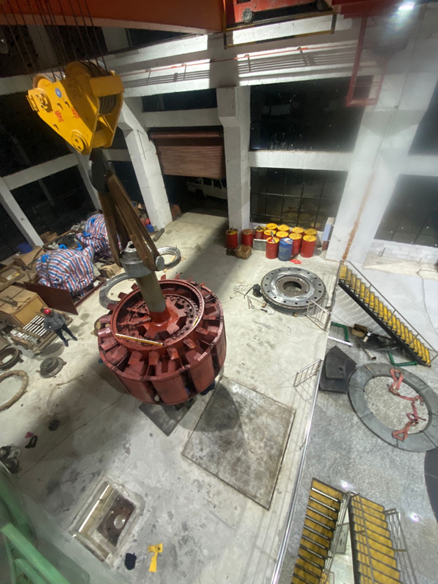
Removed the thrust collar from the unit using the EOT crane.
Overhauled the Upper Bracket using EOT crane.
Removed the protective cover that had been put over the rotor and stator.
Removed the coupling bolts from the coupling between the runner shaft and the generator shaft.
Using a dial gauge and a hydraulic bolt tensioner, measured the pressure and elongation of the coupling bolt.
After releasing the coupling bolt, lowered the runner shaft level.
Removed the generator’s rotor.
(*Note: On Day 2, runner along with shaft will be overhauled, the shaft sleeve will be removed, the connection bolt between the runner and turbine shaft will be released then reassembled with the new runner and all the parts will be overhauled.)
Reference Images:
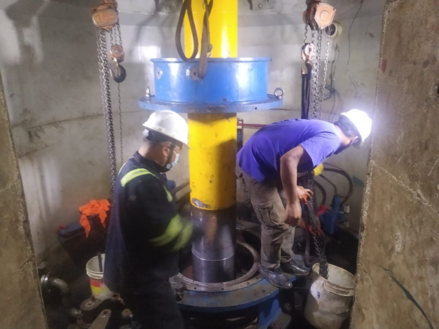
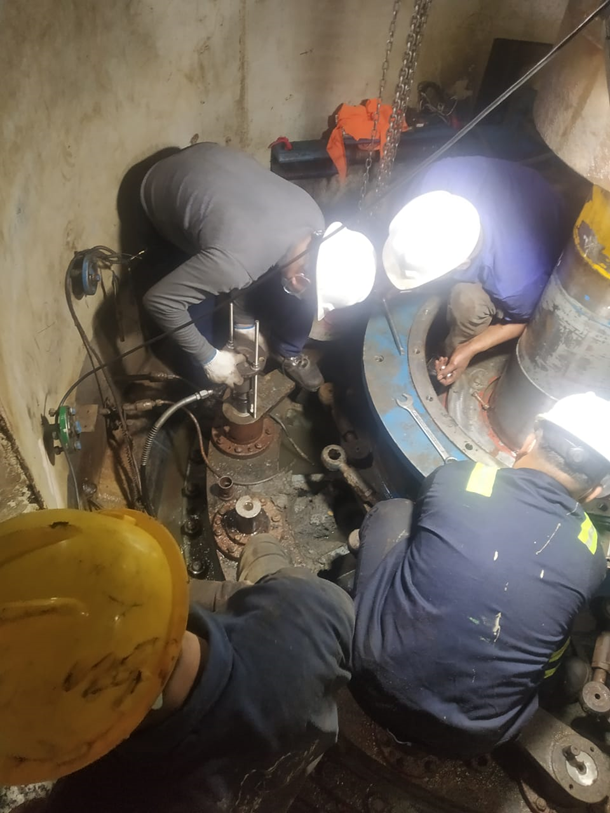
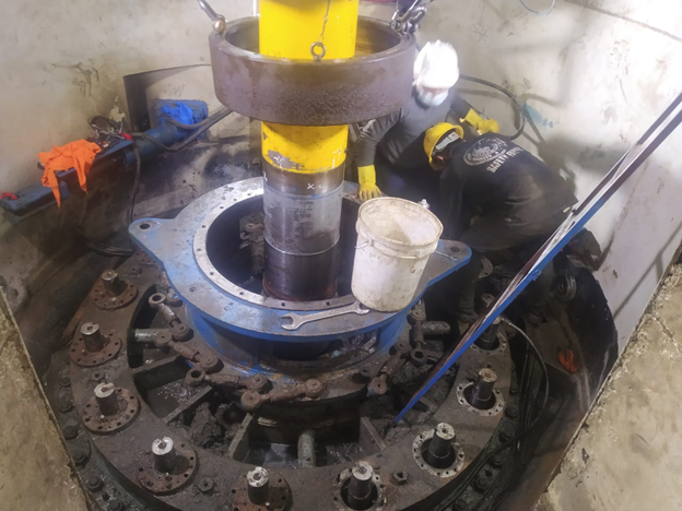
Image 1: Overhauling Floor Assembly
Image 2: Disconnecting the RTD sensors
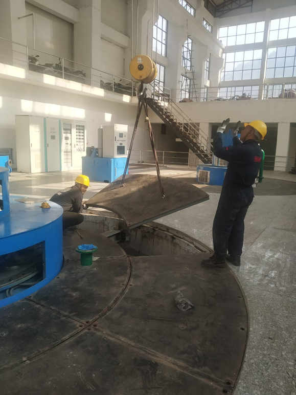
Image 3: Overhauling Turbine Guide Bearing Top Cover Assembly
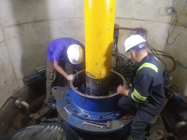
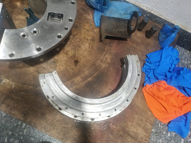
Image 4: Overhauled Turbine Guide Bearing
Image 5: Dismantled Rotating Oil Cover
Image 6: Dismantling Guide Vane Arm
Image 7: Dismantling Guide Vane Bush
Image 8: Disconnecting RTD Sensor from Upper Guide Bearing